MOGO: A Fully-Soft Ball-and-Socket Connector for Modular Soft Robotics
Yujia Liu, Rohan Singh, Hongfei Liu, Brady Stump. Carnegie Mellon University, course 24-673, December 2025. Written in the format of an IEEE RoboSoft extended abstract.
This is the paper behind the MOGO project. The project page tells the build story; this page follows the paper: the problem it defines, the method, the measurements and what they do and do not show. The full paper is available as a PDF.
Abstract
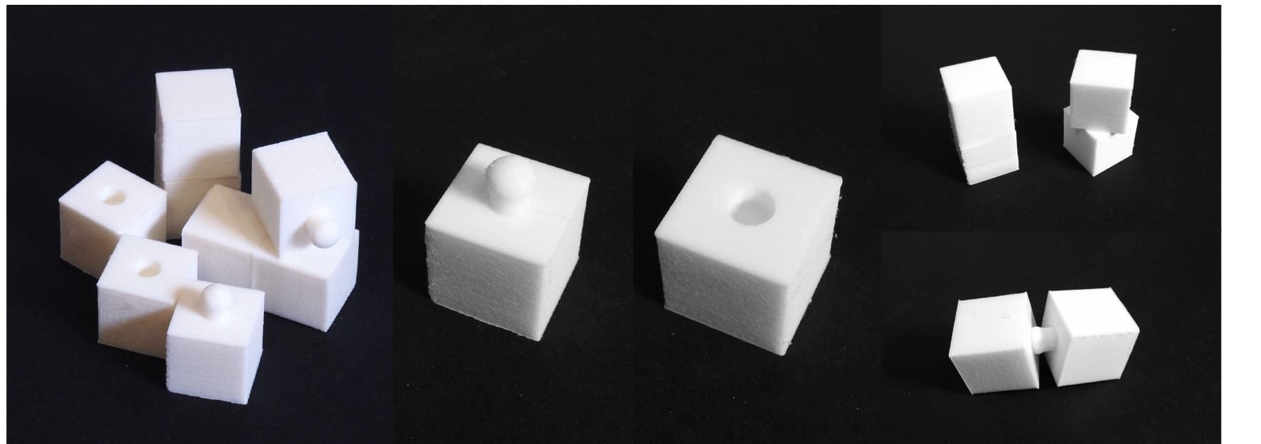
Modular soft robotics promises rapid prototyping through reconfigurable building blocks, yet existing systems suffer from what we call the Connector Compliance Paradox: rigid connectors, with a Connector Compliance Ratio (CCR) above 100, create stress concentrations at the soft-rigid interface. We present MOGO, a ball-and-socket connector system that reaches CCR ≈ 1 by building both halves from a single material, thermoplastic polyurethane (TPU). The key insight is that connector compliance enhances rather than degrades robustness: soft sockets conform to the ball under load, increasing contact area and creating vacuum-assisted retention. Through iterative prototyping from SLA interlocking ribs to FDM ball-and-socket joints, we developed an infill strategy of 20 to 30% rectilinear sockets for easy insertion (25 N) paired with 50% gyroid balls for high retention (55 N), a force ratio of 2.2. FEA characterized the failure modes under torsion (unlock at about 45°), bending and tension. The system survives more than 500 assembly cycles and assembles in about 2 seconds, showing that fully soft modular connectors are viable for reconfigurable soft robotic assemblies.
I. Introduction
Soft robots offer safe human interaction, conformable grasping and continuous deformation that rigid machines cannot match, but soft robotics remains largely confined to specialized labs. Each application is still custom engineered from concept to fabrication, which shuts out researchers, educators and makers without dedicated soft robotics expertise.
The motivating question is simple: what if building a soft robot were as intuitive as assembling LEGO bricks? LEGO works because its connections are at once trivial to make and mechanically robust. That combination has stayed elusive in soft robotics, because the compliance that makes soft robots useful works against the connection reliability that modularity needs.
Our own project started on actuation, with cable-driven bending through flexible modules. Building those prototypes showed that actuation was not the bottleneck. The unsolved problem was how modules connect to each other repeatably and strongly while staying soft, and the paper is about that connector.
II. The Connector Compliance Paradox
A literature review turned up a consistent pattern: every surveyed modular soft system joins its soft modules with rigid or semi-rigid connectors. To make the mismatch comparable across systems we defined the Connector Compliance Ratio:
CCR = E_connector / E_module
where E_connector and E_module are the elastic moduli of the connector and module materials.
| System | Module material | Connector material | CCR |
|---|---|---|---|
| Soft LEGO (Lee et al., 2018) | Tango (about 1 to 10 MPa) | ABS (about 2000 MPa) | 200 to 2000 |
| Soft Origami LEGO (Jiao et al., 2024) | E630/E650 elastomer | Rigid plastic | >100 |
| Interlock print (Benyahia et al., 2022) | Agilus30 (about 0.3 MPa) | 3D printed plastic | about 5000 |
| MOGO (ours) | TPU (about 20 MPa) | TPU (about 20 MPa) | 1 to 10 |
Existing systems sit between 100 and 5000: connectors two to four orders of magnitude stiffer than the parts they join. The mismatch concentrates stress at the material boundary, turns each joint into a rigid node that limits how the whole assembly can deform, and makes the soft-rigid interface the first place to fail under repeated loading.
Research question. Can a single-piece, all-soft connector maintain high mechanical strength across multi-axis loading while remaining user-assemblable?
III. Materials and Methods
A. Design evolution through three manufacturing phases
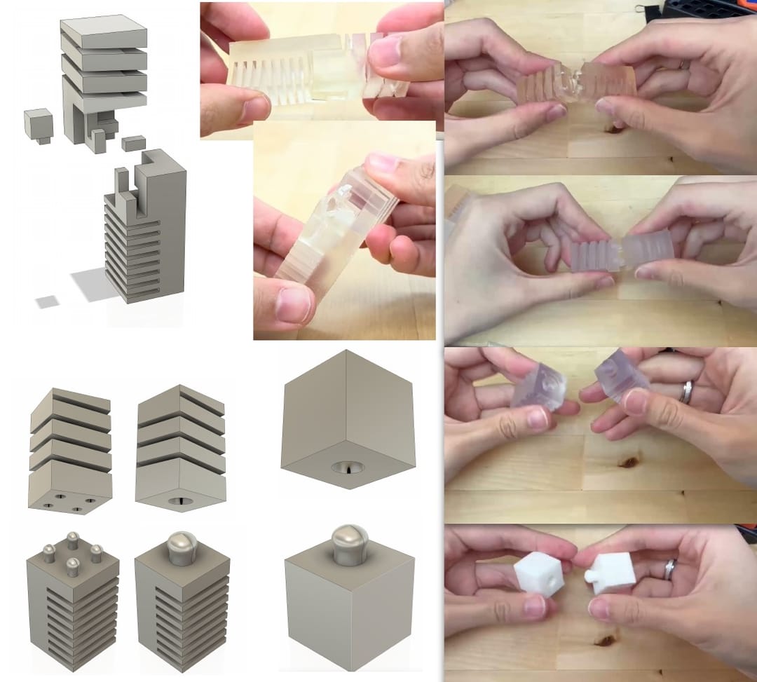
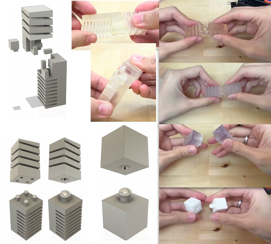
Phase 1, SLA interlocking ribs. The first prototypes drew on computationally designed mechanical interlocks, using multi-part assemblies of ribbed structures that interfere when pressed together. They were printed on a Formlabs SLA printer in Flexible Resin 80A, then IPA washed and UV cured. The parts were flexible but hard to attach reliably, and a multi-part assembly defeated the ease-of-use goal.
Phase 2, simplified SLA structures. The second phase simplified the geometry while varying parameters: LEGO-style studs of several diameters combined with ribbed interfaces, plus central through-holes for possible cable routing. The parts stayed flexible but still needed precise orientation to assemble, which rules out novice users.
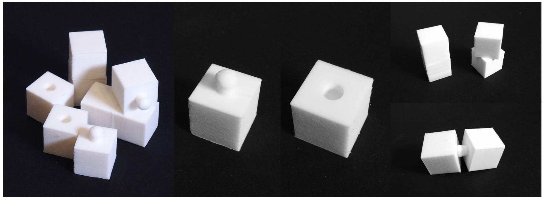
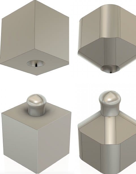
Phase 3, FDM ball-and-socket. Those two lessons changed both the process and the geometry. We moved to FDM printing in TPU on an Anycubic Kobra 3 and to a ball-and-socket joint. The rounded ball and tapered socket guide themselves together, the spherical contact spreads load, the compliant walls accept angular misalignment, and each module prints as one part with no post-print assembly.
B. Infill engineering
The socket and the ball have opposite stiffness requirements. The socket must deform enough to admit the ball while still pushing back elastically, so its rim wants low stiffness. The ball must hold its shape under insertion compression and pull-out tension, so it wants high stiffness. A conventional design would meet those needs with two materials, which is exactly what creates the paradox. Moving to FDM made a third option available: keep the material fixed at TPU and tune local stiffness through infill.
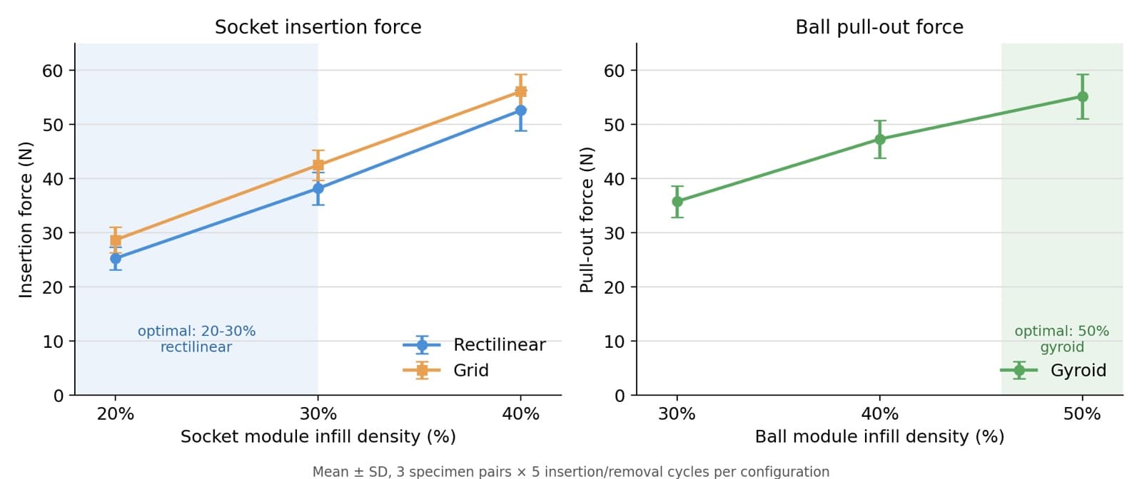
- Sockets were printed at 20%, 30% and 40% infill in Rectilinear and Grid patterns.
- Balls were printed at 30%, 40% and 50% infill in Gyroid, chosen for its near-isotropic, triply periodic structure that resists collapsing in any one direction.
Three specimens were made per condition, and each pair went through five insertion and removal cycles.
C. Finite element analysis
Structural analysis used SOLIDWORKS Simulation with a nonlinear static solver. TPU was modeled as a Mooney-Rivlin hyperelastic material with C10 = 0.69 MPa, C01 = 0.173 MPa and a density of 1.12 g/cm³. The mesh used second-order tetrahedral elements (24,847 nodes, 15,234 elements) with curvature-based refinement at the contact surfaces, and TPU-on-TPU contact friction was set to µ = 0.4.
The three load cases were tied to human-factors data so that the magnitudes match real handling:
| Load case | Applied load | Basis |
|---|---|---|
| Torsion | 4 to 5 N·m | Hand-tight torque for an average adult, from NASA anthropometric data |
| Bending | 0.50 to 2.54 N | Relaxed keyboard-key activation force up to peak typing force |
| Tension | Variable | Pull-out resistance along the ball axis |
D. Force testing
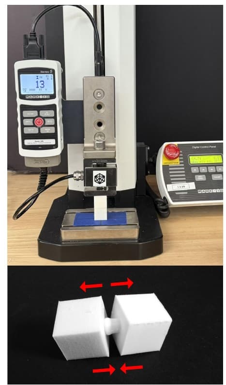
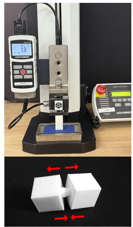
Each module pair was mounted on a Mark-10 Series 5 digital force gauge on a motorized Mark-10 test stand, in peak-capture mode, with the base module fixed and the stand driving the mobile module at about 10 mm/min. Two values were recorded per pair: insertion force, the peak force to seat the ball (the user’s assembly effort), and pull-out force, the peak force to separate the modules (retention strength).
IV. Results
A. Socket insertion force
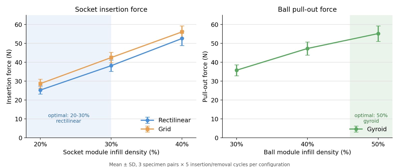
| Socket infill | Rectilinear (N) | Grid (N) |
|---|---|---|
| 20% | 25.3 ± 2.1 | 28.7 ± 2.4 |
| 30% | 38.2 ± 3.0 | 42.5 ± 2.8 |
| 40% | 52.6 ± 3.7 | 56.1 ± 3.2 |
Insertion force rises steeply with infill and is lower for Rectilinear at every density. Rectilinear’s parallel lines let the socket rim expand radially more easily than Grid’s interconnected cells. Going from 40% to 20% Rectilinear cuts insertion force by more than half.
B. Ball pull-out force
| Ball infill (Gyroid) | Pull-out force (N) |
|---|---|
| 30% | 35.8 ± 2.9 |
| 40% | 47.3 ± 3.5 |
| 50% | 55.2 ± 4.1 |
Pull-out force rises with ball infill. Gyroid spreads stress evenly and keeps the ball from collapsing locally and squeezing out of the socket. The gain shrinks toward 50%, as the ball starts to behave like a solid part.
C. Optimal configuration
The two trends compete: anything that makes the socket easier to enter also risks weakening retention. Infill engineering resolves this by assigning each requirement to a different part. A 20 to 30% Rectilinear socket paired with a 50% Gyroid ball gives
η = F_pull-out / F_insertion = 55.2 / 25.3 ≈ 2.18
so separating the joint takes more than twice the force of making it, the easy-in, hard-out behavior a stable assembly needs.
| Metric | Target | Achieved |
|---|---|---|
| Pull-out force | >30 N | 55 N (50% Gyroid ball) |
| Insertion force | <40 N | 25 N (20% Rectilinear socket) |
| Force ratio η | >1.5 | 2.18 |
| Assembly time | <5 s | about 2 s |
| Cycle durability | >100 cycles | >500 cycles, no visible wear |
| Misalignment tolerance | >10° | about ±15° |
D. FEA results
| Load case | Applied load | Finding |
|---|---|---|
| Torsion | 4 to 5 N·m | Progressive separation at about 45° of rotation, with rising resistance as a tactile warning |
| Light bending | 0.50 N | Minimal stress, stable connection |
| Heavy bending | 2.54 N | Adequate safety margin, no failure |
| Tension | Variable | Progressive disengagement rather than abrupt failure |
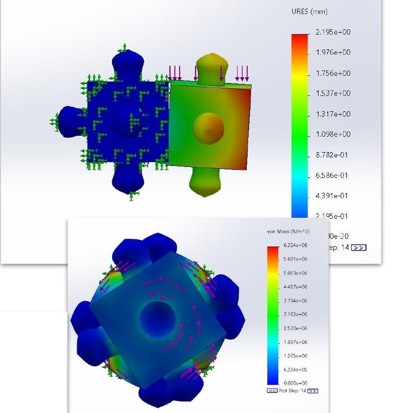
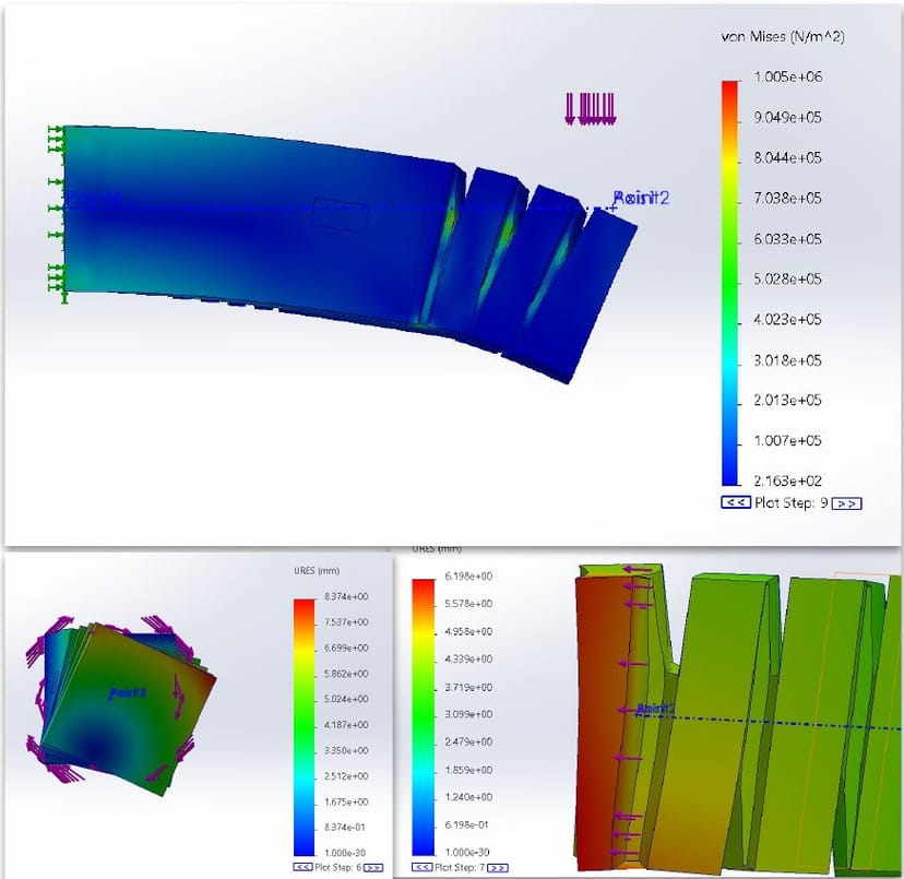
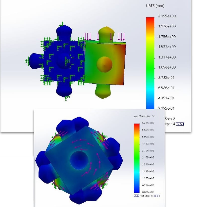
The same solver also explains why the Phase 1 and 2 interlocks were abandoned. In the ribbed SLA lamella under cantilever bending, von Mises stress gathers at the rib roots and peaks at about 1.0 MPa while the rest of the body stays near the bottom of the scale. The cross-shaped interlock connector under engagement load peaks at about 6.3 MPa at the interlock fingers, with up to 2.2 mm of displacement. Sharp interlock features concentrate stress the same way a stiffness mismatch does, while a smooth spherical contact has no such features to concentrate it.
E. Negative results
| Failure | Observation | Response |
|---|---|---|
| Torsional weakness | Unlocks at about 45° of rotation | Needs a rotational constraint, such as keying or magnets |
| Manufacturing variance | ±0.3 mm in features | Design for larger tolerances |
| Combined loading | 60% strength loss compared with single-axis loading | Always test multi-modal stress states |
The most instructive failure was tolerance. The first TPU connectors, dimensioned straight from CAD, did not fit. The root cause was too little design tolerance combined with a hyperelastic model that did not yet capture the printed TPU. The lesson is that soft materials need 2 to 3 times the design tolerance of rigid parts, and that simulations need checking against physical material tests before the geometry is frozen.
F. The surprising result: compliance enhances robustness
The most counterintuitive finding is that the connector’s softness makes the connection stronger, through four mechanisms:
- Increased contact area. Soft socket walls conform to the ball under load, giving a larger contact patch than a rigid socket allows.
- Stress distribution. Load spreads across the whole curved contact instead of concentrating at discrete points.
- Misalignment tolerance. The connector self-aligns during insertion and tolerates about ±15° of angular misalignment, against about ±3° for a rigid snap-fit.
- Vacuum retention. As the socket deforms during pull-out it forms a brief partial vacuum, adding pneumatic retention on top of mechanical interference.
This runs against the usual assumption that connection strength requires a rigid connector.
V. Discussion and Limitations
Taking the research question clause by clause: the connector is single-piece, with both modules printed as single parts; it is all-soft, with CCR ≈ 1 from uniform TPU; and it is user-assemblable, at about 2 seconds per joint, ±15° of tolerance and an audible click on engagement. High strength across multi-axis loading is only partly met. Tension (55 N) and bending are strong, but torsion is limited by the 45° unlock, which is a property of an unkeyed ball-and-socket rather than a build defect.
Other limits: only one connector type has been shown, the modules are passive with no actuation or sensing, and testing covered single joints rather than multi-module assemblies. The 60% strength loss under combined loading is a reminder that real assemblies will see loads the per-axis tests did not capture.
VI. Conclusion
MOGO shows that the Connector Compliance Paradox can be resolved. A uniform-TPU ball-and-socket reaches CCR ≈ 1 to 10 where existing systems sit above 100, and infill engineering separates easy insertion (25 N) from strong retention (55 N) within one material, a force ratio of 2.2, with about 2 second assembly and more than 500 cycles of durability. The central insight is that compliance, shaped correctly, is a source of connection strength rather than a cost. The 45° torsional unlock is the clearest next problem, pointing to keyed ball-and-socket variants or magnetic augmentation for rotational constraint, followed by a library of connector types and a multi-module assembly built entirely from MOGO joints.
Author Contributions
- Yujia Liu: ideation, writing, 3D modeling and printing, manufacturing process development.
- Rohan Singh: literature research, FEA simulation, writing, investigation.
- Hongfei Liu: ideation, conceptualization, 3D modeling, writing.
- Brady Stump: mechanical ideation, FDM expertise, 3D modeling.
References
- O. Yasa et al. (2023). An overview of soft robotics. Annual Review of Control, Robotics, and Autonomous Systems, 6, 1-29.
- J.-Y. Lee, J. Eom, W.-Y. Choi, and K.-J. Cho (2018). Soft LEGO: Bottom-up design platform for soft robotics. Proc. IEEE/RSJ IROS, 7513-7520.
- Z. Jiao et al. (2024). Soft Origami LEGO: Vacuum-actuated origami modules with all-soft connectors. Science Advances, 10(8).
- Y. Benyahia et al. (2022). Computationally designed mechanical interlocks for multi-material printing. Advanced Engineering Materials, 24(5), 2101561.
- NASA Anthropometric Source Book, citing E. Asmussen and K. Heeboll-Nielsen (1961). Isometric muscle strength in relation to age in men and women. Ergonomics, 4(1), 17-26.
- T. Armstrong et al. (1993). A conceptual model for work-related neck and upper-limb musculoskeletal disorders. Scandinavian Journal of Work, Environment and Health, 19(2), 73-84.
- C. Zhang, P. Zhu, Y. Lin, Z. Jiao, and J. Zou (2020). Modular soft robotics: Modular units, connection mechanisms, and applications. Advanced Intelligent Systems, 2(6), 1900166.