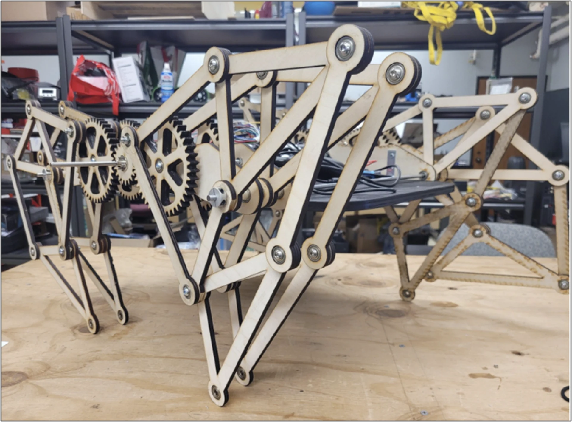
Theo Jansen’s Strandbeests are wind-powered kinetic sculptures that walk on beaches. Sails catch the wind, and that energy turns a crank that drives his Jansen linkage legs, which turn rotation into a surprisingly lifelike walking gait. In Spring 2023, a six-person team of us at Texas A&M TURTLE Robotics set out to build a motor-driven version as a fun showcase robot for the club.
The Linkage
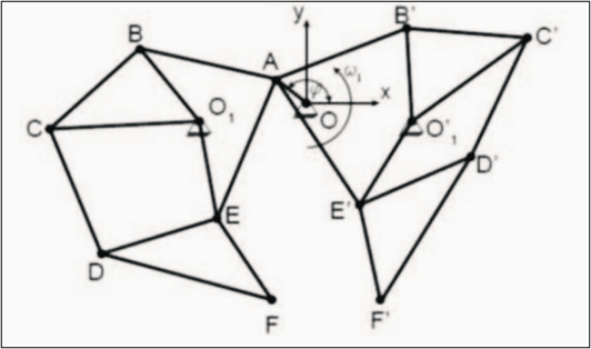
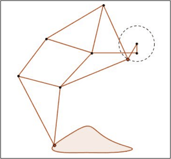
The whole robot depends on getting the leg geometry right. A Jansen leg is a single degree of freedom mechanism: one crank rotates and every other joint follows, tracing a foot path that is flat along the bottom (the stance phase, when the foot pushes on the ground) and lifts clear on the return (the swing phase).
Our initial research settled three things before any CAD:
- the ideal leg linkage dimensions, from the existing research on Jansen’s linkage,
- the leg configuration, meaning how many legs to run and how to phase them around the crank so some feet are always on the ground, and
- the motor requirements: low speed and high torque, since the crank turns slowly and has to lift the whole body.
Design and Fabrication
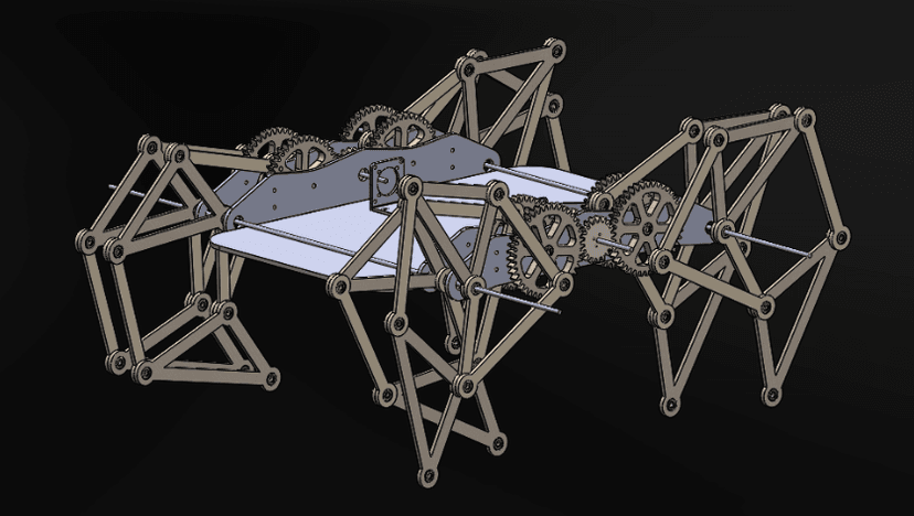
We modeled everything in SolidWorks, scaling the research dimensions into real parts. The final assembly has 8 leg assemblies driven through 4 gear assemblies.
- Gears and leg linkages: laser cut.
- Chassis: a base plate cut on a scroll saw and painted, with laser-cut side plates.
- Hardware: 6 mm steel axles running in 6 mm ID bearings, with a variety of spacers to keep each linkage layer in its own plane.
Control System
The electronics are deliberately simple:
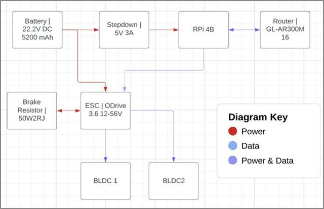
- a 22.2 V, 5200 mAh battery feeds an ODrive 3.6, with a brake resistor to absorb regenerated energy, driving two brushless motors,
- a CUI AMT10 encoder (8192 CPR) gives the ODrive closed-loop feedback,
- a 5 V, 3 A step-down powers a Raspberry Pi 4B running Debian Bullseye, and
- a small travel router puts the Pi on its own network.
The Pi talks to a pygame dashboard over WebSockets, so the robot can be driven and monitored from a laptop.
What We Would Change
At the end of the semester, our list of changes for the next iteration was:
- Increase joint stability. Each leg has many pinned joints, and play in each one adds up at the foot.
- Add feet so it can walk on softer or uneven surfaces.
- Add ribs across the base plate for stiffness, and reduce the weight of the main chassis plate.
- Add sensors and autonomous operation. This version is driven by hand from the dashboard.
For me, the project was a lesson in how much a mechanism’s behavior lives in its geometry. The motors only turn cranks, so the gait is decided by link lengths and phasing in CAD long before any control code runs, and most of what we wanted to fix afterward was mechanical: stiffness, tolerances and weight.