The Maze Bot was a Texas A&M TURTLE Robotics project that I led with a five-person team split into mechanical and software groups. The goal was a small wheeled robot that could find its way out of a maze it had never seen, using a 2D LiDAR to see the walls. The maze itself was meant to be reconfigurable: a pegboard grid with walls and shapes that pin into it, so we could change the layout between runs.
This page covers what we actually finished: the hardware design and a path planner for the case where the whole maze is known. The robot was still being assembled when the project wrapped up, and the full unknown-maze solver, localization and control software were never built.
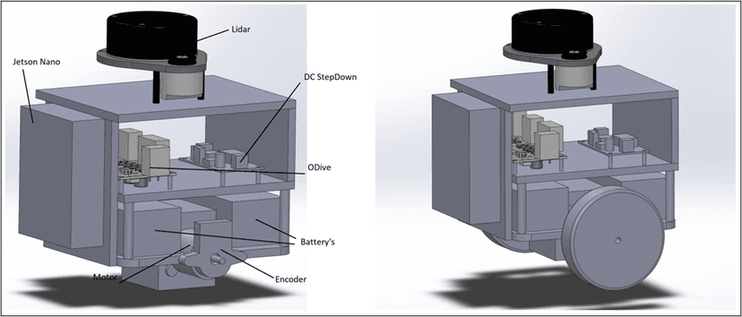
Hardware
The parts list for the final design:
- Motors: 750Kv brushless motors. That is far too fast for a maze robot at the wheel, so they had to be geared down.
- Encoders: 8192 CPR, for accurate wheel odometry.
- Motor control: an ODrive 3.6, which handles closed-loop velocity control and lets us command velocity profiles directly instead of raw PWM.
- Power: a DC step-down converter from the battery to 5 V at 3 A for the compute and sensor side.
- Compute and sensing: a Jetson Nano running Jetson Linux 18.04 with a WiFi module, and an RPLidar A1 mounted on top.
Mechanical Design
On the mechanical side, the main design work was fitting the drive train and electronics into a compact chassis in CAD.
- We settled on a 6:1 gear reduction between each motor and its wheel, trading the motors’ excess speed for torque.
- The base was remodeled around the motor mount, with slots that locate both the base plate and the motor’s rotor.
- We added a full frame that holds every electrical component: the Jetson, ODrive, step-down converter, batteries and encoders, with the LiDAR on a mast at the top.
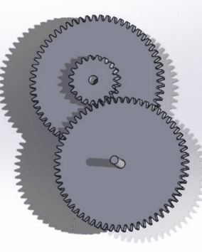
The major parts went to the campus 3D printing service, and end-of-semester queues delayed them. That delay is where the build stalled: the next steps on our final deck were finishing the prints, assembling the electronics into the printed frame and building the maze.
Path Planning for a Known Maze
The software group, working in ROS 2 Humble, broke the problem down. The full task (no assumptions about maze shape, goal somewhere on the boundary and visually marked) is hard, so we first solved the subproblem where the entire maze is known.
- Fast-marching trees (FMT*) sample the free space and find a piecewise linear path from start to goal.
- Bezier curves replace the sharp corners. The curves are joined at the endpoints of the linear segments, and the polygon formed by each curve’s control points is constrained to lie inside free space. A Bezier curve always lies inside the convex hull of its control points, so that constraint guarantees the smoothed path does not clip a wall.
- TOPP-RA (time-optimal path parameterization based on reachability analysis) turns the geometric curve into a trajectory, producing position, velocity and acceleration profiles that respect the robot’s limits.
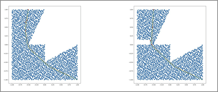
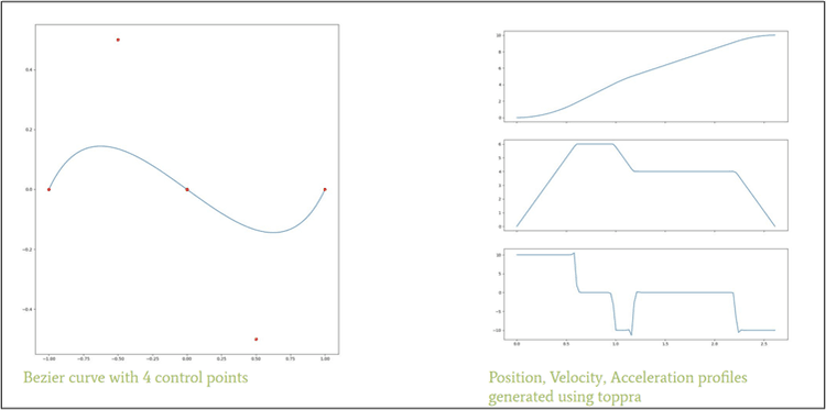
The plan for the full solver was to apply the known-maze planner iteratively to whatever part of the maze the LiDAR had revealed, and to follow a boundary until it either closed into a shape or reached the exit.
Where It Ended
Honestly, this one did not reach the finish line. When the project wrapped, the remaining work was:
- extending the planner to a partially known maze,
- writing the control software that would track the TOPP-RA trajectories on the ODrive,
- LiDAR localization, and
- a Gazebo simulation of the maze.
What I took from it was the planning pipeline itself: splitting a hard problem into a subproblem we could actually solve, and leaning on a geometric property like the Bezier convex hull to get a collision guarantee without extra checks. As lead, the print delay also taught me to put long-lead fabrication at the start of the schedule, not the end.