Bio-inspired Fish Locomotion Through Variable Undulation
This project investigates the optimization of aquatic robotic propulsion through bio-inspired fishtail locomotion. Our team developed and evaluated a multi-actuator system to understand the fundamental relationships between control complexity, swimming pattern variables, and propulsion efficiency in underwater robotics.
Research Motivation
Currently, underwater robots lack the efficiency and maneuverability of aquatic creatures observed in nature, which would benefit defense and wildlife protection efforts that seek improved propulsion methods. Traditional propeller-based systems, while widespread in maritime applications, often create significant wake signatures, consume substantial energy, and struggle with complex maneuvering in confined spaces.
Our research addresses this gap by investigating fish-inspired locomotion as an alternative propulsion mechanism. Fish have evolved over millions of years to achieve remarkable propulsion efficiency, making them ideal models for bio-inspired robotics.
Research Hypothesis
Our core hypothesis was: A high frequency, low amplitude tail motion will move the robot faster and in a more stable manner than a low frequency, high amplitude pattern.
This hypothesis was inspired by observations of different fish swimming patterns in nature and the biomechanical principles that govern efficient aquatic locomotion.
Project Overview
Underwater robotics has seen significant advancements in recent decades, yet achieving efficient propulsion mechanisms that mimic the capabilities of biological organisms remains a significant challenge. The significance of this research extends to both robotics and biology communities:
- For robotics, efficient underwater propulsion systems are crucial for applications in marine exploration, environmental monitoring, and underwater infrastructure maintenance
- For biology, our research provides insights into the mechanics of fish locomotion, helping to bridge the gap between theoretical understanding and practical implementation
Our approach focused on:
- Developing a fish-like robot that effectively replicates fish swimming patterns
- Systematically analyzing how different oscillation parameters affect propulsion
- Bridging the gap between theoretical understanding and practical implementation of bio-inspired locomotion
Biological Inspiration
Fish locomotion provides an excellent biological model for underwater propulsion due to its evolutionary optimization for efficiency and maneuverability. Fish typically exhibit one of several swimming modes:
- Anguilliform: Eel-like, with whole-body undulation
- Carangiform: Propulsion concentrated in the posterior half
- Thunniform: Propulsion primarily from a stiff caudal fin
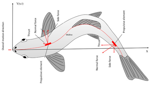
These locomotion patterns involve complex interactions between the fish’s body and the surrounding fluid, creating thrust through manipulation of water pressure and momentum. As shown in our reference diagram, forward thrust is generated when the lateral movement of the fish’s body creates regions of pressure differential in the surrounding water.
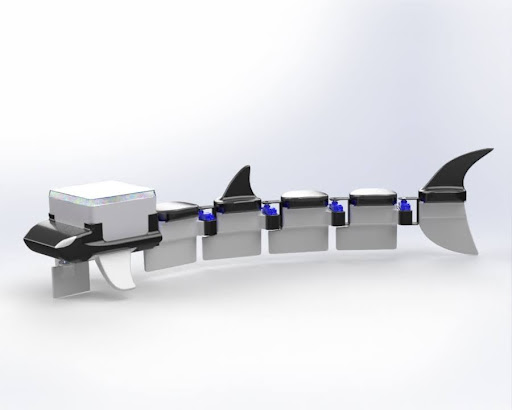
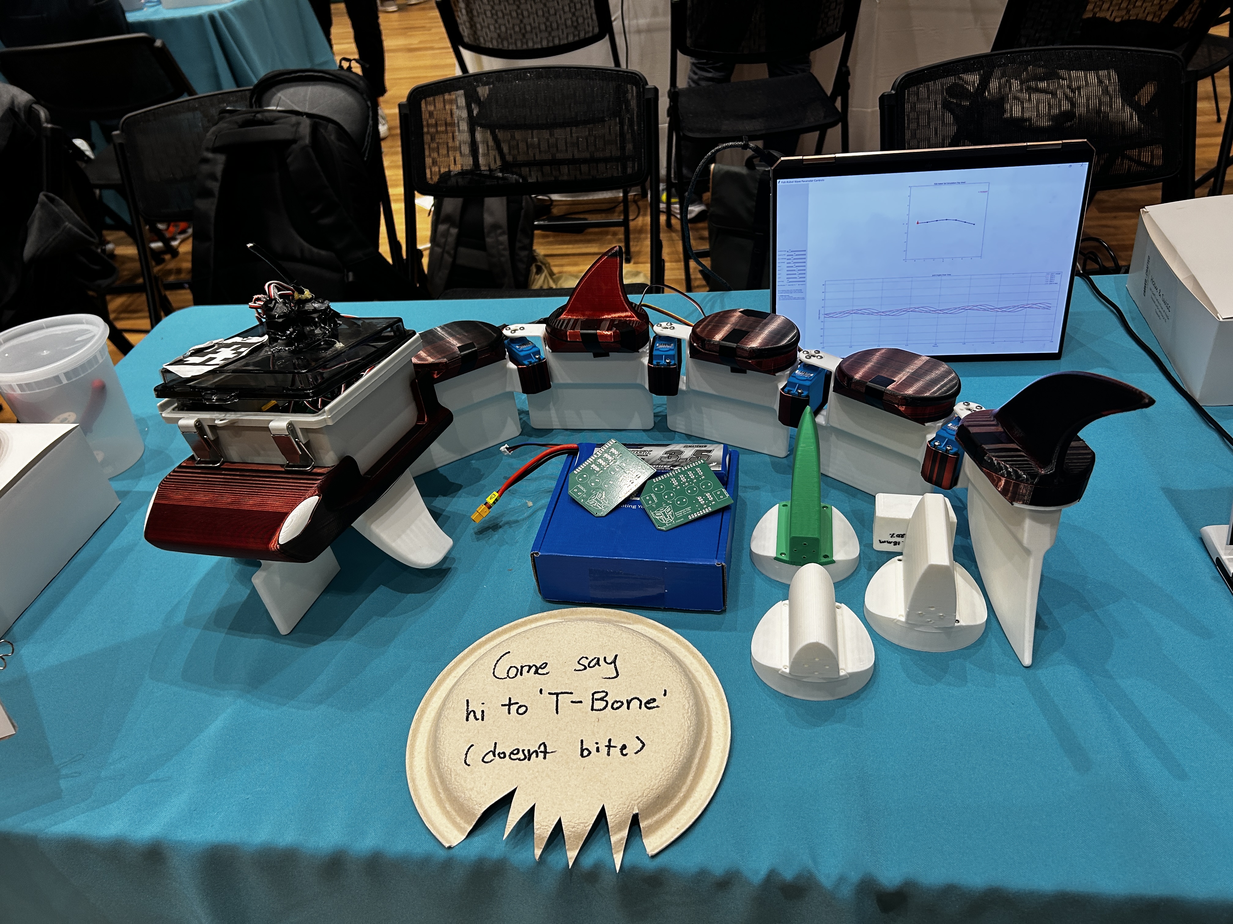
Robot Design: T-Bone
Our robot design, named T-Bone, consists of three main components: the head, the tail, and the electronics. The overall structure was developed to enable modular testing of different tail configurations while maintaining consistent measurement and control capabilities.
Head Design
The head serves as the primary electronics housing and tail attachment point, featuring:
- A streamlined, shark-inspired hydrodynamic shape optimized through CFD analysis to minimize drag forces
- Watertight electronics enclosure positioned above the waterline for system safety
- Lateral stabilizing fins to counter rotational forces during swimming, positioned at the bottom of the enclosure raft
- A dedicated servo-actuated rudder mechanism for directional control
- Mounting points for AprilTag markers used in visual tracking
Fabricated using 3D printing with PLA material at 15% infill, the head achieves sufficient buoyancy while maintaining structural integrity. Waterproofing was accomplished through silicone sealant application at all seams and potential leakage points, creating a robust platform that balances multiple functional requirements.
The electronics enclosure was secured to a specially designed raft structure that maintained the sensitive components above the waterline while allowing the propulsive elements to operate effectively underwater.
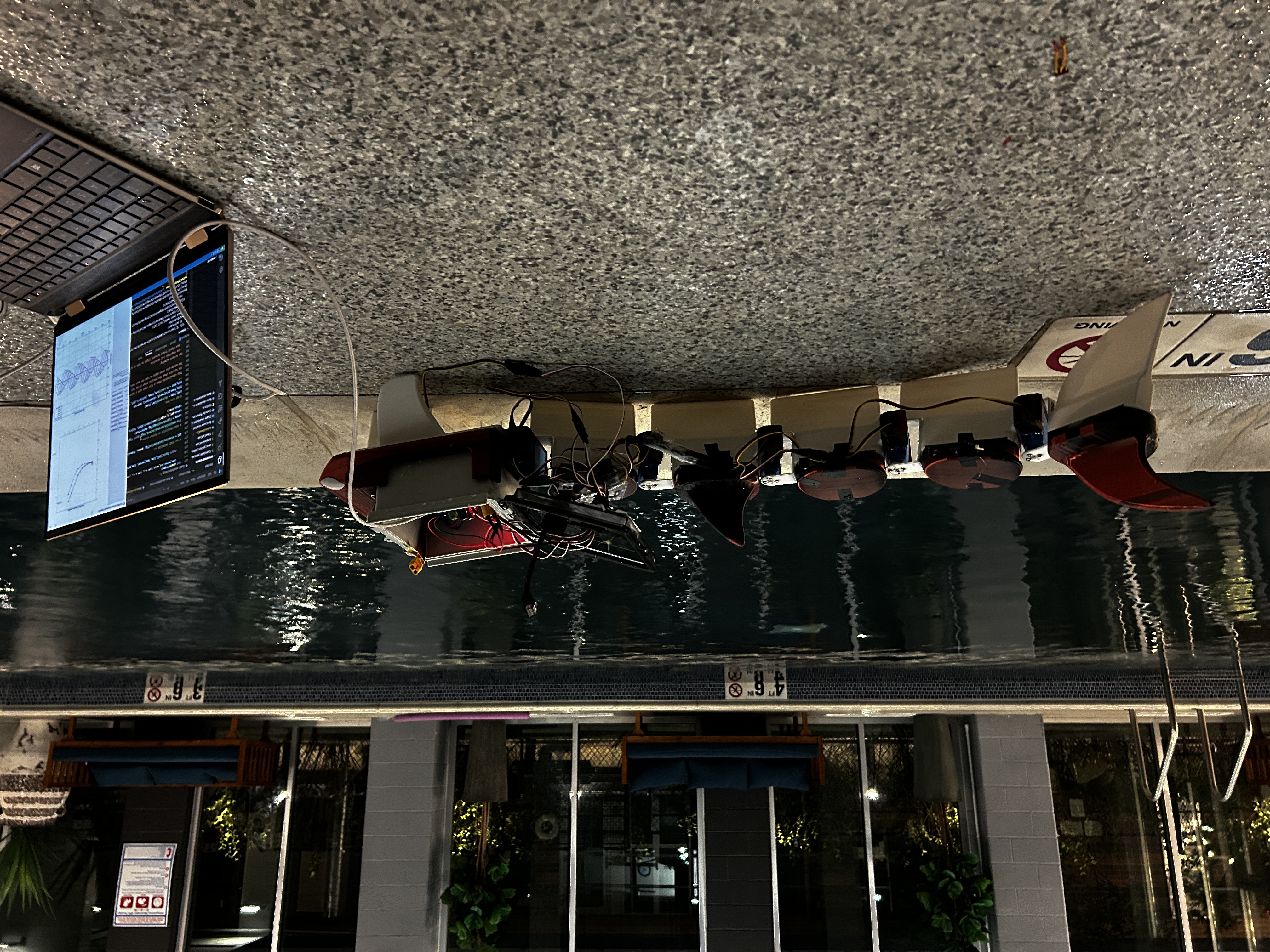
Modular Tail System
The modular tail system represents our design’s core innovation, enabling comparative testing of different actuation approaches:
- Five identical segments connected by interchangeable joints, allowing adjustment of the robot’s overall length and flexibility
- Active multi-actuator system with waterproof HiTec D646WP servo motors in each joint allowing precise control of segment angles
- Vertical fin elements with maximized surface area at the posterior end, mimicking the caudal fin structure of carangiform swimmers
- Segments 3D printed at varying infill percentages (10% for horizontal, 80% for vertical) to achieve neutral buoyancy when assembled
The tail was designed with two distinct fin components:
- Horizontal buoy fins: Provides buoyancy and stability
- Vertical propulsion fins: Maximizes surface area for thrust generation during undulation
This design allows for precise control of segment angles to generate complex wave patterns along the tail. The system was designed with modularity as a priority, allowing us to easily swap different tail components for comparative testing.
Electronics Architecture
The electrical system consists of:
- Arduino Uno R4 controller: Provides central processing and servo control via 6 digital pins
- 2S 7.4V 3500mAh LiPo battery: Supplies 18 minutes of operation time at 70% of servo stall current (calculated with 1.5 safety factor)
- Custom PCB: Features six PWM, power, and ground pin sets for simplified servo wiring, debugging LEDs, and efficient power management
- Six D646WP waterproof servo motors: Five for tail articulation and one for rudder control
- Electrical switch for battery connection to reduce wear on connectors and enable quick power cycling
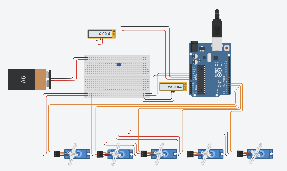
The circuit was designed with ample current handling capacity, with copper pour on both sides of the PCB to manage the peak current of up to 11A from the servos. The board includes bulk and decoupling capacitors (220µF for every 1A) to ensure stable power delivery.
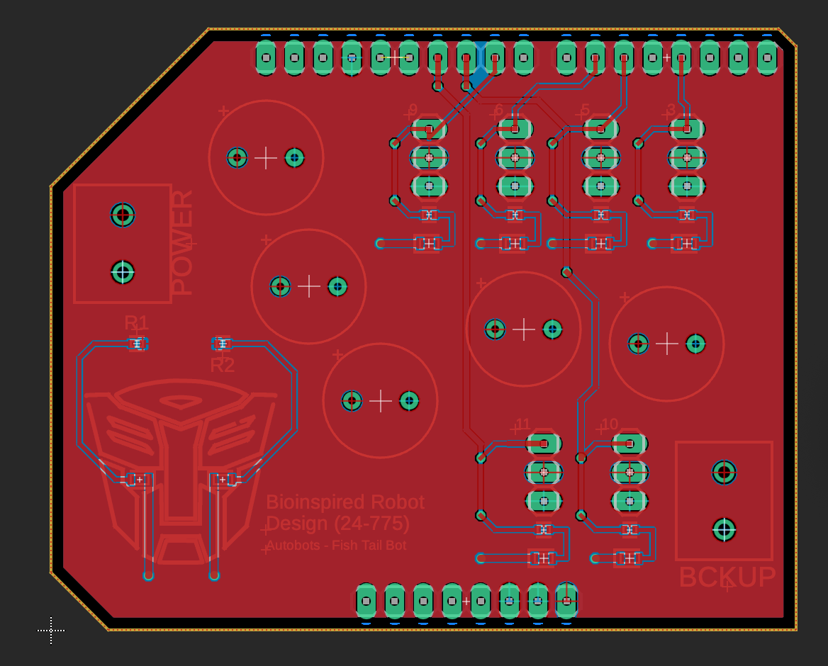
All connections were waterproofed using cord grippers embedded in the top of the enclosure and sealed with FlexSeal. The electrical components were housed in a verified off-the-shelf waterproof enclosure, with the Arduino R4 and custom PCB securely mounted inside.
Technical Approach
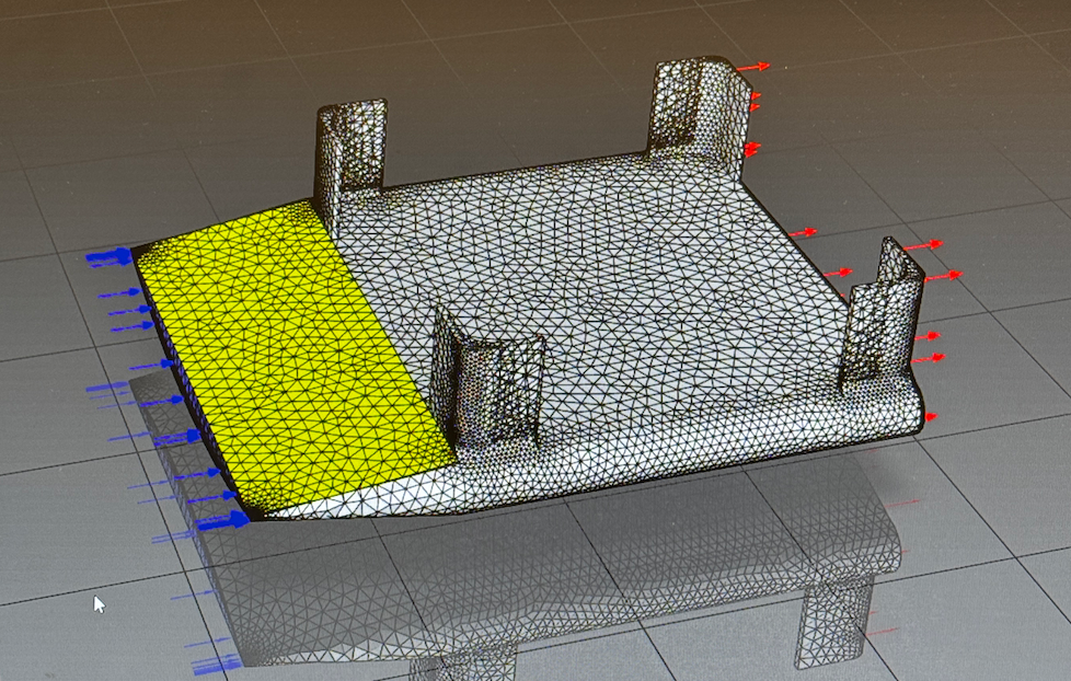
Computational Fluid Dynamics (CFD)
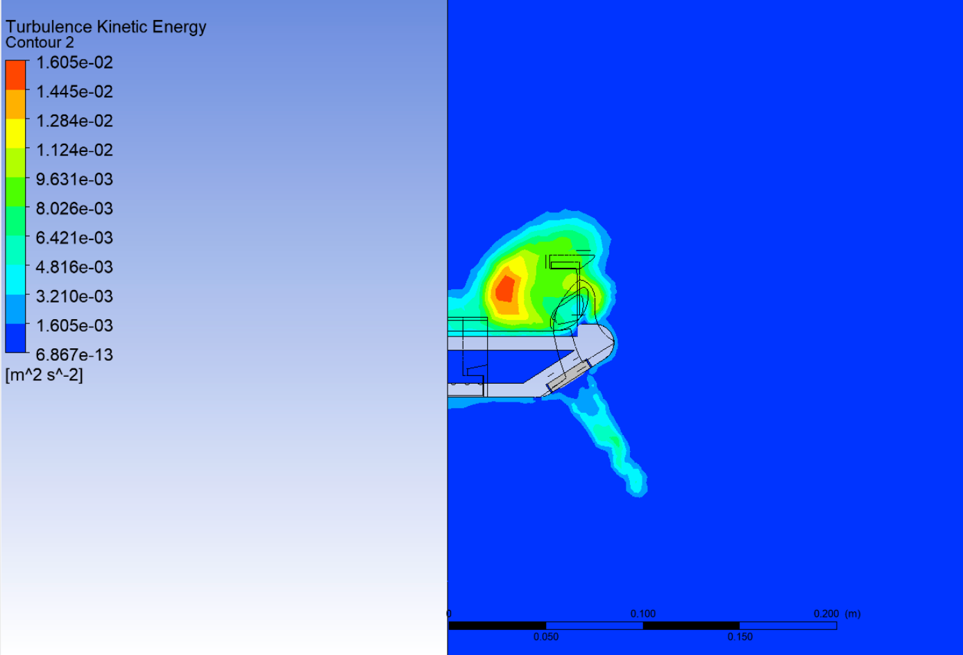
A comprehensive CFD study was conducted to optimize the robot’s hydrodynamic properties, particularly focusing on the head and fin designs:
- Initial mesh refinement study: Tested element sizes from 0.005m to 0.15m, normalizing around drag force calculations, with convergence occurring at 0.015m element size
- Fin geometry analysis: Different fin designs (length: 2”, 2.5”, 3”) and curvatures (2” and double-curved variants) were simulated to evaluate performance
- Turbulent Kinetic Energy (TKE) measurement: Used as a key metric to determine the “efficiency” of fins in aiding forward propulsion while minimizing unnecessary turbulence
- Velocity streamline visualization: Enabled analysis of vortex formation in the wake of different designs
The fin length of 2.5” with 2” curvature showed the best performance, with an average TKE around 7-9 × 10^-3 m²/s². This optimal design showed a complete turbulence profile without points of excessive TKE that would indicate regions of turbulence detrimental to efficient propulsion.
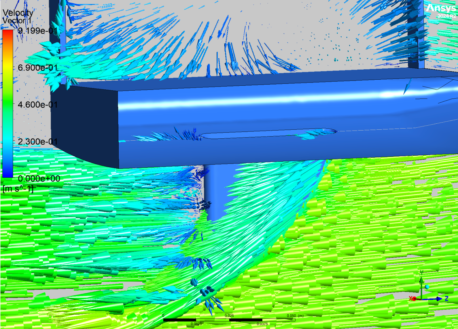
The final robot design incorporated fins at a diagonal angle from the head’s base, which CFD analysis confirmed generated a complete turbulence profile in the wake at a moderate range (around 8 × 10^-3 m²/s²) - acceptable for propulsion without creating regions of high turbulence.
Buoyancy Optimization
To determine the most effective infill density for buoyant 3D-printed parts, we conducted controlled float tests using PLA cubes printed at different infill percentages:
- 15% infill: Floated with approximately 90% volume submerged
- 30% infill: Floated with approximately 60% volume submerged
- 50% infill: Floated with less than 50% volume submerged
- 100% infill: Sank completely
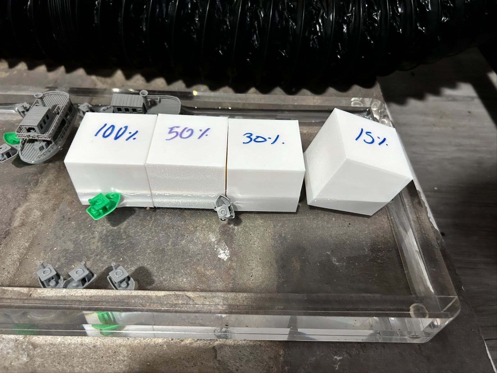
Based on these results, we designed a two-part fin structure:
- Horizontal elements printed at 15% infill for maximum buoyancy
- Vertical elements printed at 80% infill to lower the center of mass
This differentiated infill strategy allowed us to control buoyancy while maintaining structural integrity of the robot. The raft supporting the electronics enclosure was printed at 15% infill to ensure it could support the weight of the components while keeping them above the waterline.
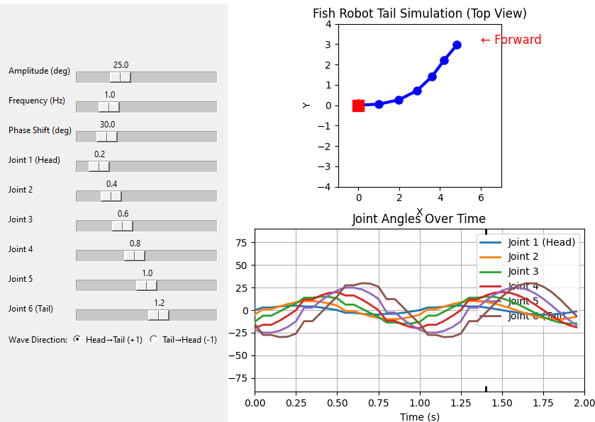
Motion Control System
The robot is propelled by sending a sinusoidal wave pattern through the tail’s servos. This swimming pattern can be altered by changing three primary parameters:
- Frequency: The speed of the wave oscillation (0.5-2.0 Hz)
- Amplitude: The maximum angle of deflection (10-25 degrees)
- Phase Shift: The progression of the wave along the tail (controls direction, 45-60 degrees)
Additionally, we implemented “tail amplitude multiple constants” that could be assigned to each joint individually, allowing for different swimming patterns:
- Constant Tail Propulsion (TP): All joints move with the same amplitude
- Multiplying Undulation (MU): Amplitude increases progressively along the tail (e.g., [0.5, 0.6, 1.1, 1.2, 1.3])
We developed an interactive Python-based simulation environment with sliders to visualize and tune these parameters in real-time before implementation on the physical robot:
# Simplified excerpt of sine wave generation for tail motion
def calculate_joint_angles(amplitude, frequency, phase_shift, tail_multipliers):
    joint_angles = []
    for i, multiplier in enumerate(tail_multipliers):
        angle = amplitude * multiplier * math.sin(
            2 * math.pi * frequency * time + phase_shift * (i+1))
        joint_angles.append(angle)
    return joint_angles
The system supports both continuous swimming and burst movement modes, with configurable burst duration and pause intervals.
Computer Vision and Tracking
Our computer vision system employs AprilTag markers (36h11 family) for real-time tracking and position estimation of the robot:
- Camera calibration: Determined intrinsic parameters with <0.4 pixel reprojection error
- Perspective transformation: Mapped pixel coordinates (u,v) to real-world positions (x,y) with ±1.2 cm accuracy
- Multi-tag tracking: Simultaneously tracked the robot head (ID 0) for position/orientation, tail segments (IDs 1-4) for joint angles, and static reference points (IDs 5-6) for path definition
- Robust filtering: Implemented algorithms to reduce noise and handle partial occlusion (maintaining tracking when up to 30% of a tag was obscured)
The system was validated through controlled movement tests where the robot followed predefined paths while the vision system recorded position data at 30fps, allowing precise measurement of swimming performance metrics including velocity, acceleration, and path deviation.
![]()
Control System
We developed two PID controllers to correct the robot’s movement by minimizing the error in its trajectory compared to a desired path:
- Heading controller: Calculates the difference between the intended and actual heading based on the angle between two look-ahead rays, adjusting the rudder position
- Speed controller: Calculates the positional error between the robot’s current and desired position, adjusting tail movement parameters
While the complete feedback control system couldn’t be fully implemented in water tests due to vision system challenges, we validated the controller logic through MATLAB and Python simulations that successfully guided the simulated robot toward intended trajectories.
Experimental Results
We conducted multiple water experiments to evaluate the robot’s performance with different swimming patterns. Our testing methodology included:
- Component-level on-land tests for buoyancy, electrical systems, and tail articulation
- Verification of buoyancy and waterproofing through monitored submersion
- Evaluation of various sine wave patterns for motion control in aquatic environments
- Testing different combinations of frequency, amplitude, and phase shift parameters
The table below summarizes our key experiment parameters and results:
| Trial | Amplitude (degrees) | Frequency (Hz) | Phase Shift (degrees) | Tail Pattern | Result |
|---|---|---|---|---|---|
| 1 | 16 | 1.5 | 60 | Constant | Stationary |
| 2 | 20 | 1.5 | 60 | Constant | Stationary |
| 3 | 13 | 2.0 | 45 | Multiplying | Forward Movement |
| 4 | 18 | 2.0 | 45 | Multiplying | Increased Forward Movement |
| 5 | 25 | 2.0 | 45 | Multiplying | Greatest Forward Movement (until bracket failure) |

The most significant finding was that high-amplitude oscillation patterns (20-25 degrees) produced more effective propulsion than low-amplitude patterns (13-16 degrees) when frequency (2Hz) and phase shift (45°) were held constant. Additionally, the multiplying undulation pattern (where amplitude increases progressively along the tail) generated much more effective forward movement than the constant tail propulsion pattern.
These results actually contradicted our initial hypothesis, demonstrating that:
- Higher amplitude was more important than higher frequency for effective propulsion
- The phase shift angle of 45° was critical for forward movement
- Progressive amplitude increase along the tail (multiplying undulation) significantly outperformed constant amplitude
Technical Challenges and Solutions
Throughout the development process, we encountered several challenges that required innovative solutions:
Weight Distribution
Challenge: Initial tests showed insufficient forward propulsion due to the head’s mass being too low relative to the tail, resulting in whole-body undulation rather than the desired concentrated tail movement. Solution: We adjusted the weight distribution by adding ballast to the head and redesigning the fin structure to provide better thrust concentration. Unlike more advanced robots like AgnathaX from EPFL (which uses force sensors to actively adjust to water conditions), our design relied solely on visual feedback through AprilTag detection.
Waterproofing
Challenge: Protecting electronic components while allowing for servo movement. Solution: Used verified off-the-shelf waterproof enclosures and servo motors, with additional silicone sealant at junction points and cord grippers for wire passthroughs. All connections between the enclosure and servos used waterproof connectors and were sealed with FlexSeal for additional protection.
AprilTag Tracking
Challenge: Tags becoming unreadable when covered with waterproofing material or affected by water. Solution: Initially, we tried to secure the tags to the fins using double-sided tape, but this proved inadequate as the tags were quickly affected by water. For future implementations, we’ve considered 3D printing the AprilTags directly using white and black filament to create waterproof markers.
Mechanical Failure
Challenge: During our fifth trial with 25° amplitude, one of the joint brackets failed, necessitating an end to the experiment. Solution: Identified that higher structural reinforcement is needed for high-amplitude oscillation patterns, particularly at the connection points between segments. Future designs will incorporate stronger materials or reinforced joint designs for these high-stress areas.
Future Improvements
Based on our findings, we’ve identified several promising directions for future research:
- Enhanced joint stability: Redesign the joint connections with reinforced brackets and bearings to reduce mechanical wear and accommodate higher amplitude movements
- Finer tuning of sine wave parameters: Conduct more extensive testing across the parameter space of amplitude (10-30°), frequency (0.5-3.0 Hz), and phase shift (30-90°)
- Advanced tail designs: Explore more biomimetic fin shapes with flexible materials to better replicate the hydrodynamic efficiency of real fish tails
- Improved tracking systems: Develop waterproof AprilTags using 3D printing with white and black filament, reducing the issues from paper tags getting wet or light reflection
- Enhanced feedback control: Implement encoders or servos with position feedback (like Dynamixels) to gain insights into how each servo responds to control signals
- Alternative computer vision approach: Explore using motion capture markers on the water surface combined with overhead cameras to improve tracking reliability
- Autonomous swimming capability: Add a Raspberry Pi to the enclosure to bridge communication between the laptop and Arduino board, enabling untethered operation
Conclusion
Through systematic experimentation, we’ve demonstrated that high-amplitude oscillation patterns (20-25°) with a specific phase shift (45°) and multiplying undulation pattern produce more effective propulsion than other parameter combinations. This contradicts our initial hypothesis that high frequency, low amplitude motion would be most efficient.
These findings provide crucial insights for developing more efficient aquatic robotic systems applicable to marine exploration, environmental monitoring, and defense applications. The modular design approach of our T-Bone robot allows for comparative testing of different locomotion strategies, making this platform valuable for both robotics research and educational purposes.
Our results highlight the importance of biomimetic principles in robotics design, showing how lessons from evolutionary adaptation can inform engineering solutions for complex problems. The project serves as a foundation for further exploration of bio-inspired underwater propulsion systems, contributing to the ongoing efforts to develop more efficient and maneuverable underwater robotics.
Video Demo
Watch T-Bone in action! This video shows our fish robot swimming and the team testing it in the pool.
References
- Lauder, G. V., Anderson, E. J., Tangorra, J., & Madden, P. G. (2007). Fish biorobotics: kinematics and hydrodynamics of self-propulsion. Journal of Experimental Biology, 210(16), 2767-2780.
- Romano, D. (2022). Development of a Novel Underactuated Robotic Fish with Magnetic Transmission System. Bioinspiration & Biomimetics, 17(2), 026004.
- Thandiackal, R., Melo, K., Paez, L., Herault, J., Kano, T., Akiyama, K., Porez, M., Ijspeert, A.J. (2021). Emergence of robust self-organized undulatory swimming based on local hydrodynamic force sensing. Science Robotics, 6(57), eabf6354.
- Lindsey, C. C. (1978). Form, function and locomotory habits in fish. Fish Physiology, 7, 1-100.