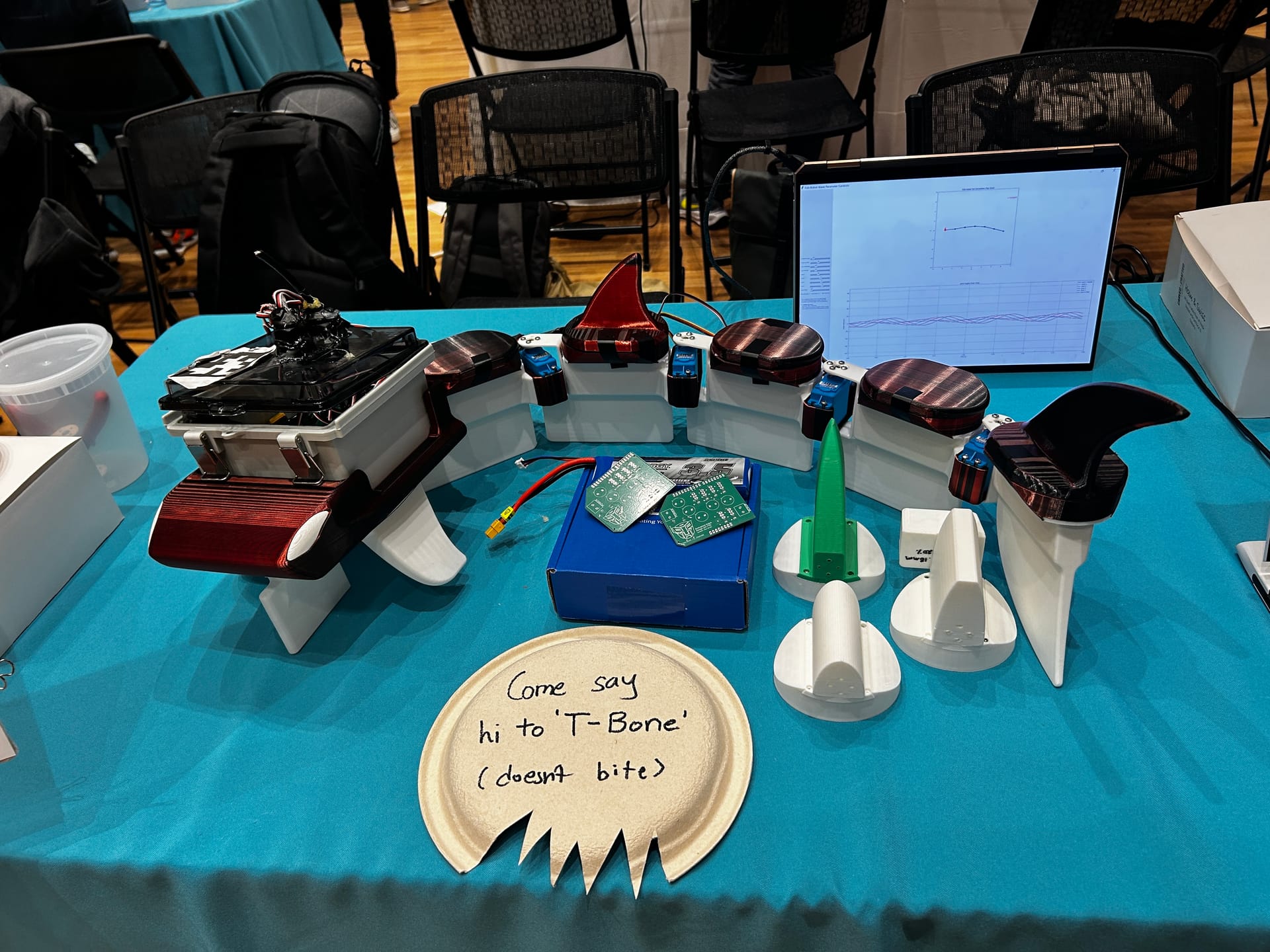
A while back I worked on a team building a robot fish. We called it T-Bone. It had a 3D printed shark shaped head, five identical tail segments, six waterproof servos, a custom PCB, and, at the poster session, a paper plate cut into a jagged mouth telling people T-Bone does not bite.
The stated goal was to study how undulation parameters affect propulsion. The actual education was different. Almost nothing I learned on that project was about control theory. It was about the fact that a swimming robot is not a robot that happens to be in water. It is a body and a fluid solving each other, continuously, and you do not get to design one of them.
I think about that project more often than I expected to, because the failure modes turned out to be the ones I hit at OctaPulse.
The Hypothesis Was Wrong and That Was the Useful Part
We wrote the hypothesis down before we built anything: high frequency, low amplitude tail motion would move the robot faster and more stably than low frequency, high amplitude motion. It sounded right. It matched the way a tuna looks when it is cruising.
The water disagreed. Five trials are on record. Trials 1 and 2 ran the tail at 16 and 20 degrees of amplitude, 1.5 Hz, 60 degrees of phase shift, with every joint moving at the same amplitude. Both were logged as stationary. Not slow. Stationary. The robot sat in the pool wagging.
Trials 3, 4 and 5 changed three things at once, which is bad experimental hygiene and I would run it differently now: 2.0 Hz, 45 degrees of phase shift, and a multiplying undulation pattern where amplitude increases along the tail rather than staying constant. Those trials moved forward, and they moved further as amplitude went from 13 to 18 to 25 degrees. The last one moved best and ended when a joint bracket broke.
So the three things we actually learned were that amplitude mattered more than frequency in our range, that the 45 degree phase shift was necessary for forward motion at all, and that progressive amplitude along the tail beat constant amplitude by a wide margin. The pattern increased amplitude from the front of the tail to the back; the example set given in our write up is [0.5, 0.6, 1.1, 1.2, 1.3].
The stationary trials are the part I would keep. A robot that wags in place is producing plenty of motion and no net thrust, which is a very direct demonstration that motion and propulsion are unrelated quantities until the fluid agrees with you.
Swimming Is a Fluid Structure Problem, Not a Trajectory Problem
A wheeled robot separates cleanly. You plan a path, you track it, and the ground is a boundary condition that mostly holds still. That separation is what makes most of robotics tractable.
Water removes it. The thrust comes from a pressure differential the body creates by pushing fluid around, so the thing you are controlling is a coupling, not a position. Change the fin geometry and you change the plant. Change the infill percentage of a printed part and you change the mass distribution, which changes the body wave, which changes the wake. There is no layer where you can pretend the fluid is somebody else’s problem.
We did the CFD work you would expect. A mesh refinement study swept element sizes from 0.005 m to 0.15 m, normalized on drag force, and converged at 0.015 m. Then we swept fin geometry, lengths of 2, 2.5 and 3 inches and two curvature profiles, scored on turbulent kinetic energy in the wake. The 2.5 inch length with the 2 inch curvature came out best, averaging roughly 7 to 9 times 10^-3 m²/s², and the fins we shipped sat around 8 times 10^-3.
That study was worth doing and it did not predict the result of a single water trial. It told us which fin to print. The CFD we ran scored fin shapes on drag and wake turbulence for a fixed geometry. It could not tell us whether a wave sent through five servos would push water backwards or just shake the body, and that gap between what the simulation covered and what the experiment asked is the single clearest lesson from the whole build.
We Settled the Buoyancy Question With Four Cubes in a Tray
The most useful measurement on the project used no compute at all.
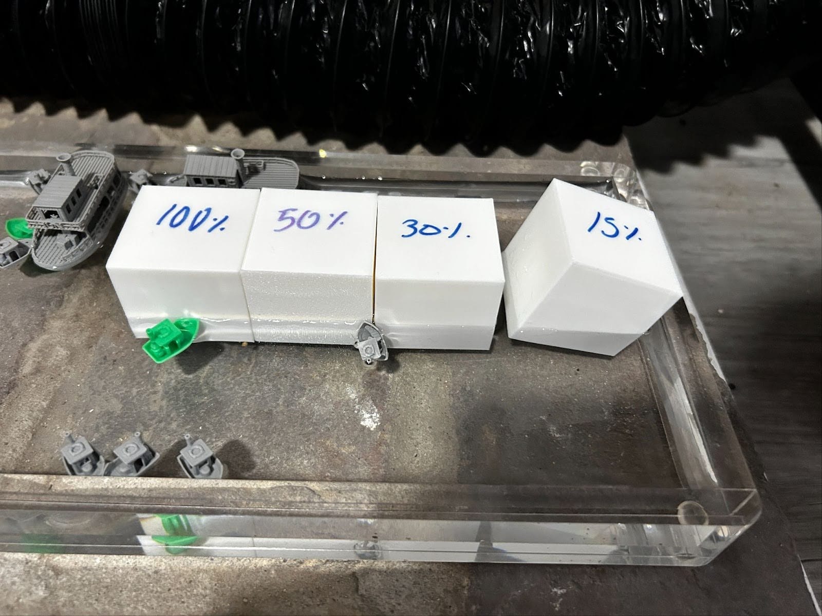
We printed PLA cubes at four infill percentages and floated them. The 15 percent cube floated. The 100 percent cube sank outright. The sweep across the four is what set the infill split across the robot.
That test set the design. Vertical propulsion fins went to 80 percent infill to pull the center of mass down, horizontal elements went much lower, and the raft carrying the electronics enclosure went to 15 percent so it could hold the battery and the board above the waterline. The head was printed at 15 percent for the same reason.
I like this one because it is the honest version of engineering judgment. We could have modeled effective density as a function of infill and print settings and been wrong in a way that took a week to find. Instead we asked the water.
The Body Fought the Tail
Our first real propulsion failure was not in software. The head was too light relative to the tail, so when the tail drove, the whole body undulated instead of the tail alone. The way I read it, the reaction torque was rotating the front of the robot instead of moving water backwards. We were feeding energy into shaking ourselves.
The fix was ballast in the head and a fin redesign to concentrate thrust. It worked well enough to swim, and it is worth naming what a better robot does instead. AgnathaX out of EPFL, described by Thandiackal and colleagues in Science Robotics in 2021, uses distributed hydrodynamic force sensing along the body so the swimming pattern self organizes against the water it is actually in. T-Bone had no force sensing at all. Our only feedback about the interaction between body and fluid was a camera looking down at the pool.
That is the whole difference between a robot that adapts to a fluid and a robot that plays a recording at one.
The Loop Never Closed, and the Reason Was Perception
We wrote two PID controllers. A heading controller drove the rudder from the angle between two look ahead rays, and a speed controller adjusted tail parameters from positional error. Both were validated in MATLAB and Python simulation, where they steered the simulated robot along the intended trajectory.
Neither ran closed loop in water. Not once.
The reason was the vision system. Tracking used AprilTags from the 36h11 family, ID 0 on the head for pose, IDs 1 through 4 on the tail segments for joint angles, and IDs 5 and 6 as static references defining the path. The project write up reports camera calibration under 0.4 pixels of reprojection error, perspective mapping to about plus or minus 1.2 cm, tracking held with up to 30 percent of a tag occluded, and recording at 30 fps. Those are our numbers from that document rather than something I can re-derive today, and they describe the system on a good frame.
What killed it was simpler than any of that. The tags were paper, attached with double sided tape. Once they got wet, or once waterproofing material went over them, they stopped being readable. A tag that half detects is worse than no tag, because the pose estimate degrades quietly rather than failing loudly. Add surface glare and ripple distortion on an overhead shot of a pool and there is no run long enough and clean enough to close a loop on.
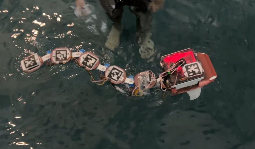
The obvious fix, which we scoped but did not build, was printing the tags directly in white and black filament so the fiducial is part of the part.
I want to be precise about what stopped us, because it is easy to tell this story as “we ran out of time.” The actuation worked. The controllers were written and simulated. The measurement layer was what failed, and everything downstream of a measurement layer is decoration.
Every Failure We Had Was Physical
Going back through the record, there are four failures worth naming, and not one of them is an algorithm.
The head was too light and the body absorbed the thrust. The paper tags died in water. A joint bracket snapped during the 25 degree trial and ended the experiment, which told us the connection points between segments needed reinforcement before the parameter sweep could go any higher. And the closed loop control never made it into the pool.
The electronics are not on that list. An Arduino Uno R4, a custom board with six PWM, power and ground sets, copper pour on both sides to carry an 11 A peak from the servos, and bulk and decoupling capacitors sized at 220 µF per amp. A 2S 7.4 V 3500 mAh pack, calculated for about 18 minutes at 70 percent of servo stall current with a 1.5 safety factor. None of that is what stopped us.
The Same Failure Modes Show Up At OctaPulse
Three of them, and I did not notice the overlap for a long time.
The first is that water breaks the vision system before it breaks anything else. Soggy paper AprilTags in a pool are a small, cheap version of a problem I spend real time on at OctaPulse, which is that wet, shiny, deformable surfaces defeat algorithms that assume stable texture and a scene that holds still. The specific failure changes. The category does not.
The second is that the fiducial belongs in the frame. T-Bone made that argument by not having a durable one. OctaPulse phenotyping images carry their own scale reference in the frame, for reasons I wrote about separately.
The third is the sequencing. Autonomy is measure, decide, act, and the fish robot is the cleanest illustration I have of why that order is not negotiable. We had actuators, we had a plant, we had controllers that worked in simulation, and none of it mattered because we could not reliably say where the robot was. That is why the measurement layer is the part I care about most now.
I would build T-Bone again. I would print the tags, reinforce the brackets first, and change one parameter at a time.